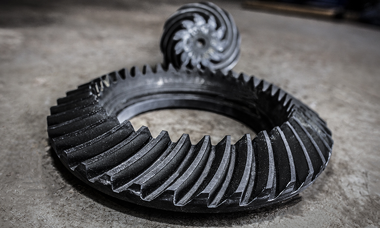
One of the first things many enthusiasts do after purchasing a new performance vehicle is set aside money to install a new shorter (numerically higher) gear ratio in the drivetrain; for late-model Mustang enthusiasts, this is just about a rite of passage. For years, the 3.73:1 ratio was the go-to cog for Mustang lovers of all persuasions, and never more so than with the 2011-current Coyote engine onboard. The high-winding, four-valve-per-cylinder engine loves to be turned into the upper reaches of the RPM band, with many enthusiasts tickling the 7,800 number on the tachometer with relative frequency when the Boss 302 or Cobra Jet manifolds from Ford Performance are used.
When the 3.73:1 gear is combined with the six-speed Getrag MT-82 transmission used in the ’11-up Mustang, the resulting combination is just about perfect for a naturally-aspirated car, both on the street and at the track. But when forced induction is added – as in the case of our subject vehicle – the 3.73 gear becomes less street-friendly.
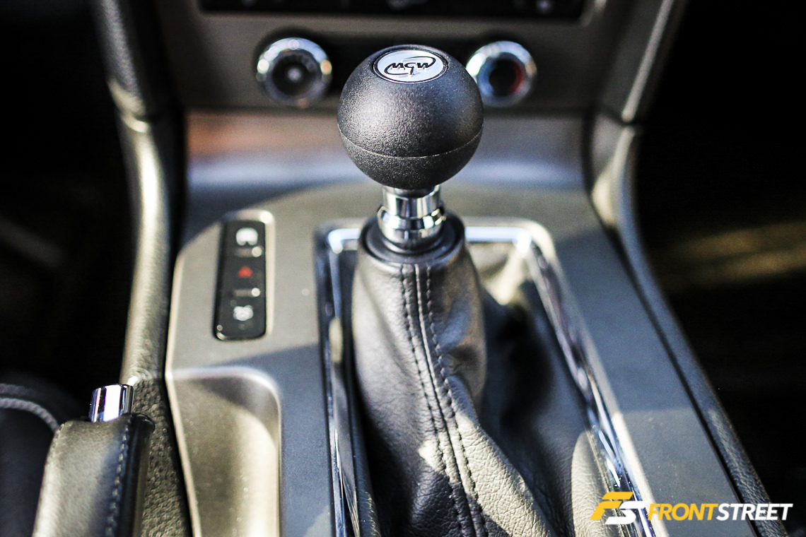
Combined with the MT-82’s super-steep 3.66 first gear ratio, we found that the 3.73:1 required lots of gear changes when cruising the car around. On the dragstrip, the 1-2 gearchange came up nearly as quick as the car was able to get out of the hole, necessitating a perfect shift every single time – and we’re just not that good. In addition, since this car is driven regularly to and from work along with plenty of weekend cruises and other trips, and there is no interest in building up a left leg the size of Popeye’s forearm, the decision was made to swap out the gear for one a step down, in the form of a set of Ford Performance 3.55:1 gears.
We used a gear ratio calculator to determine the proper gear ratio to use with the 28.0-inch tall tires used at the strip, and the 3.55 ratio came in perfectly, showing 132 mph through the top of fourth gear at 7,400 rpm. This car is expected to run 132-134 mph through the quarter with the ProCharger P1-SC-1 onboard, so if an extra 100-200 rpm is required in fourth gear to cross the stripe, it should work out perfectly.
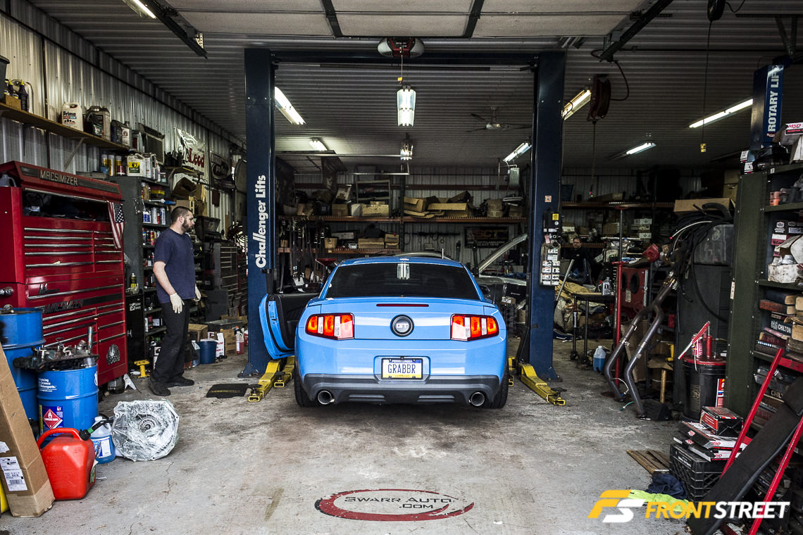
We recently made the trip to Swarr Auto in Collegeville, Pennsylvania, to have the 3.55s installed and watch the longtime Mustang modification specialists at Swarr do their thing on our rear end.
Taking Parts Out, Putting New Parts In
The installation process for Mustang with live-axle rear suspension has barely changed over the years; ever since the 8.8-inch housing was placed under the Mustang in 1985, the process remains largely the same. Although the suspension changed underneath the 2005-’14 Mustang to include the three-link design with panhard bar and single upper control arm, the actual gear replacement portion of the install follows the same principles.
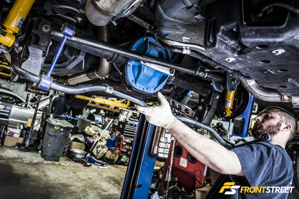
Removal of the sway bar is required; the panhard bar is also removed to gain access to the housing’s innards. Here Swarr Auto’s Anthony Pappas pulls the sway bar out of the car. There are two fasteners at the top, plus the clamps on each side where the bar is secured to the bracket on the rearend housing.
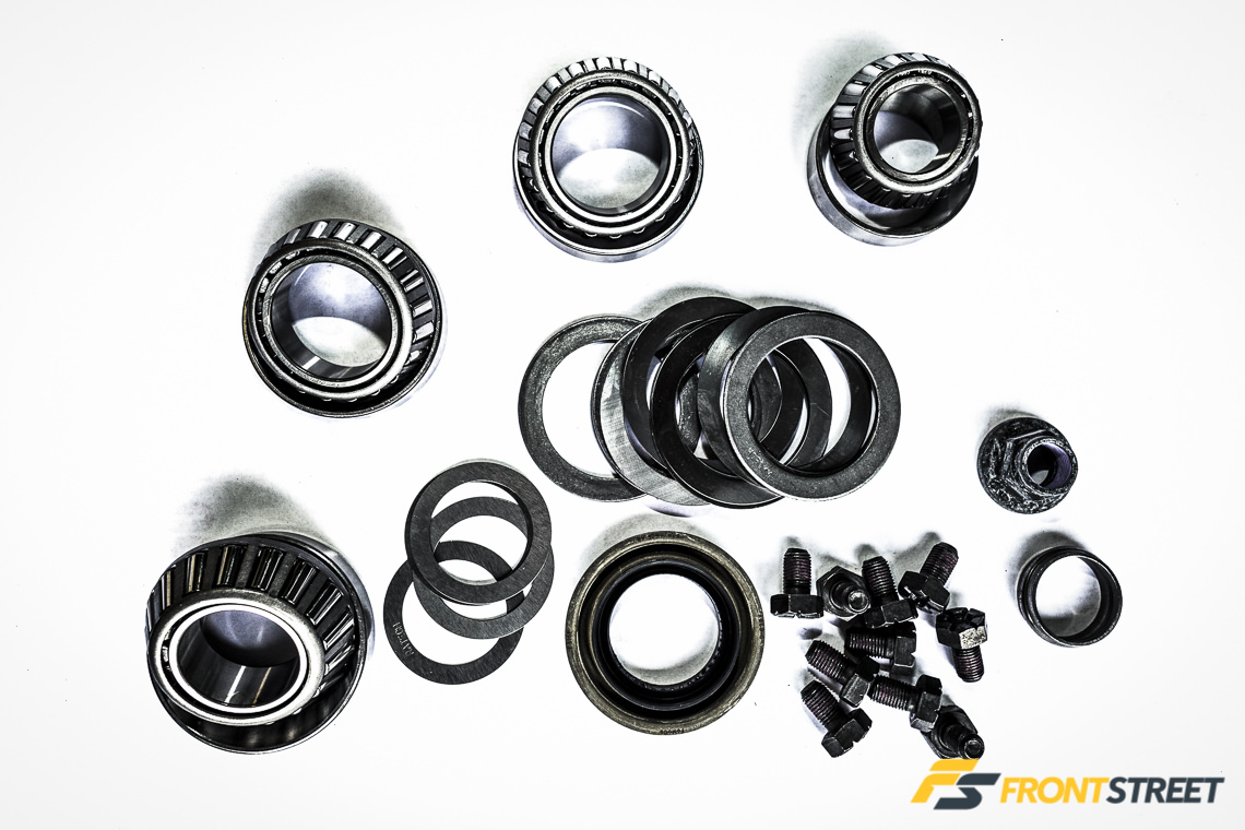
The gear installation kit (M-4210-B2) from Ford Performance includes everything we needed – a pair of carrier bearings, the high-torque 2012 GT500 pinion bearing, and the outer pinion bearing, along with new ring gear bolts, pinion and carrier shims, a new pinion seal, pinion nut, and crush sleeve.
One fastener at each end of the panhard bar eases removal of that component. Pappas then moves to pull the differential cover and expose the guts.
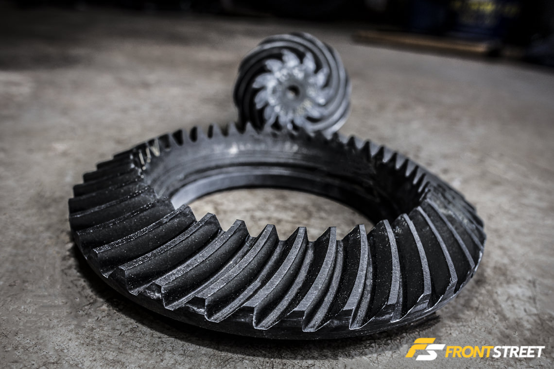
There are a number of manufacturers of 8.8-inch rear gears; over the years we’ve used Ford Performance exclusively in a number of Mustangs and have been pleased with their performance. Swarr Auto proprietor Eric Swarr swears by them, especially when it comes to quiet operation.
(Left) Once the cover is loose, the old fluid is drained. Stand back here – the stench of gear oil is not something you want to wear all day. (Right) The first step to removal of the differential is to remove the lock pin, and once that’s out, the the shaft in the center of the differential is removed. Prior to these steps, the brake calipers and mounts should be removed from each end of the rear, and the rotors placed aside to provide unfettered access to the axles.
(Left) Once the pin is out, then each axle is pushed inboard, one at a time, to provide room for the c-clip axle retainers to be pried out. (Right) Pappas makes use of a magnet to ease removal.
It’s important that the bearing caps are kept on the same side of the carrier when removed and replaced – here the housing and caps are marked with a hammer-strike steel hand stamp by Pappas to prevent any confusion when it’s time to put everything back together.
(Left) The retainer caps are pulled, and the differential is removed from its home. (Right) Note the thick carrier shim still in place against the housing. The shim just sits in place between the carrier and housing when the carrier is installed. Varying the thickness here is how the backlash is adjusted – more on this later.
(Left) Note the notch behind the bearing race – this provides a place for Pappas to place the tip of his punch to drive out the race for replacement with the new one from the kit. (Right) after the bearings and races are knocked out, Pappas runs sandpaper over the bores to ensure there are no burrs or other imperfections that might affect the new bearing’s performance.
(Left) Here’s one of Swarr’s tricks to ease the installation process of the new ring gear – a hotplate that has one purpose only – to heat the new ring gear so it slides right onto the differential. Eric Swarr says that snugging the ring gear down with the bolts is a big no-no, as it will stretch the ring gear bolts and could cause them to fail prematurely. (Right) Swarr pressing the old gear off; this press has been around for decades and was built right here in the shop. He replaces the cylinder every couple of years when it fails, but the structure itself is bulletproof and has seen its fair share of gear swaps. Swarr told us they do several of these per week.
(Left) Another trick of the trade – the hole in the table allows the differential to be dropped right into place, without wrestling with the gear and differential. (Right) Swarr locks the ring gear bolts down at 84 pound-feet of torque. The bolts have threadlocker preinstalled, so he doesn’t add to it.
(Left) Pappas pressing the old pinion bearing from the pinion – this is done to access the original pinion shim, which is used with the tool in the photos below to gain a starting point for installing the new gears. (Right) In this case, the shim with .029-inch thickness was appropriate for installation behind the pinion bearing.
Many shops don’t have one of these. This pinion depth tool greatly simplifies the gear installation process and ensures the pinion depth is correct as quickly as possible.
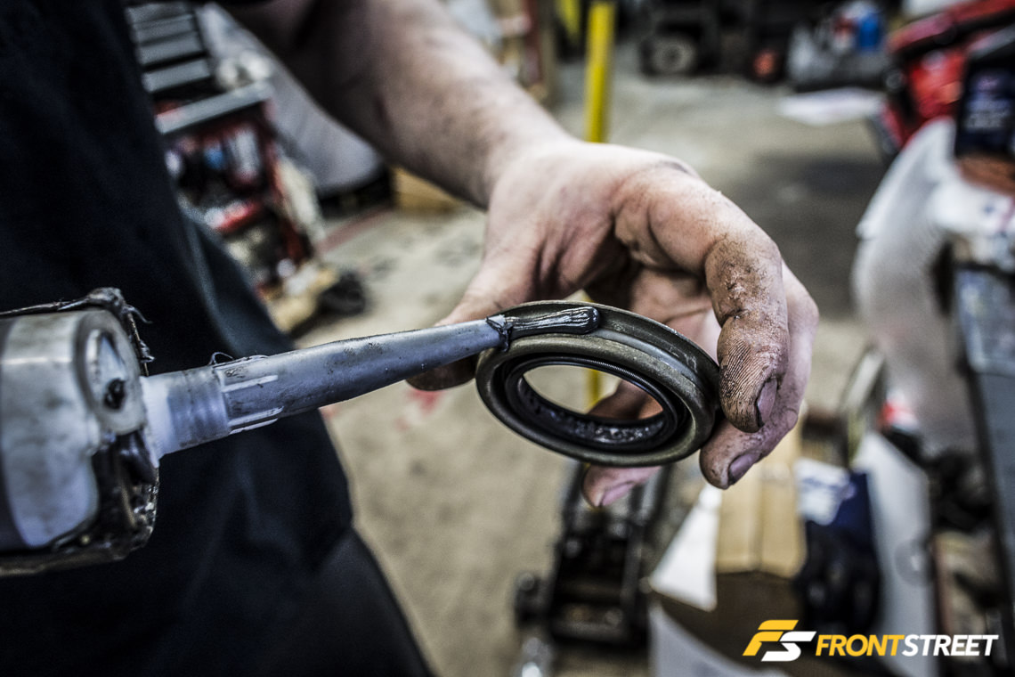
Pappas likes to use sealant around the rim of the pinion seal, because nobody wants to have to take an entire gear installation apart to fix a leaky seal.
(Left) The new pinion set up with the shim, bearing, and crush collar, ready for reinstallation into the housing. We used the crush collar supplied with the installation kit; many hardcore racers prefer to install the pinion with a solid spacer in this position instead. (Right) More threadlocker is used inside the pinion nut.
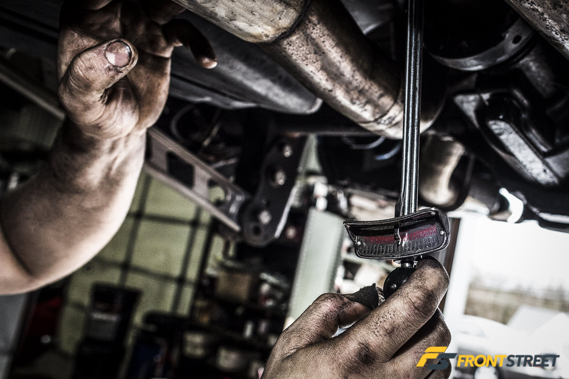
Since the pinion depth has been established with the specialty tool, Pappas locks down the pinion and crushes the collar into place. An inch-pound torque wrench is used here to determine the proper amount of drag on the bearing, which is between 16 and 28 inch-pounds. Ours is set at 18 inch-pounds. When tightening down the pinion nut, it’s very easy to go past the right spot and crush the collar too far. If this happens, the pinion must be removed, the crush collar replaced, and the process begun anew. Pappas says this part of the install is done by feel – he’s completed hundreds of gear installations over the years and still misses the mark every now and then.
With the pinion installed, it’s time to move into the critical portion of the installation – setting the backlash properly. Prior to reinstalling the differential assembly, Pappas measured the thick factory shims that were removed in the beginning of the process to determine his starting point.
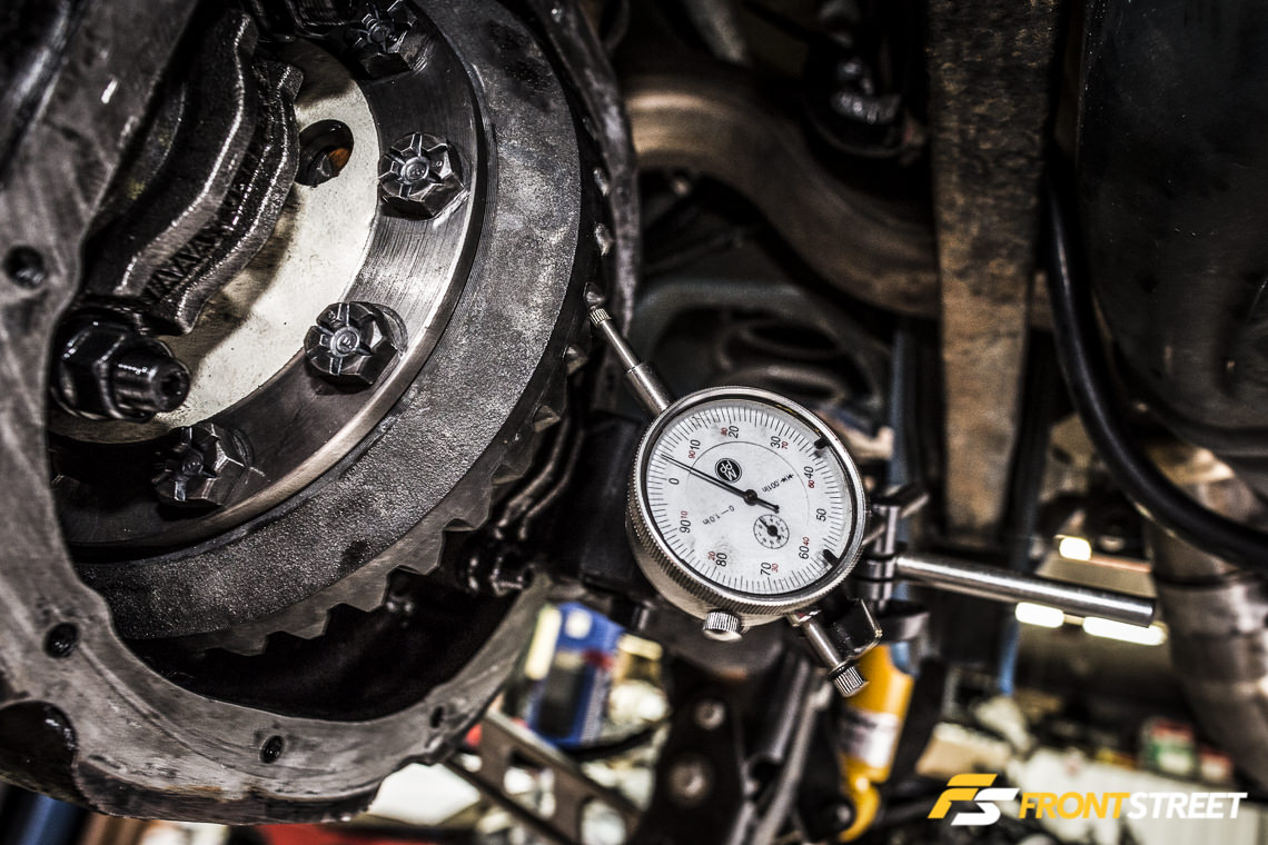
Simply reinstalling the differential as it was removed, with a .271-inch shim on one side and .282-inch shim on the other did not achieve the desired result, as the backlash with this combination of shims produced .004 backlash. Backlash is defined as “the space between the thickness of a gear tooth and the width of the space between teeth in the mating gear, designed to allow for a film of lubricant, binding from heat expansion and eccentricity, or manufacturing inaccuracies.”
The proper amount of backlash prevents the gear teeth from jamming together and making contact on both sides of the gear teeth. If there is not enough backlash for a given gear profile, noise, overloading, overheating of the gears and bearings, and seizure/failure may occur. Excessive backlash will cause noise, which is exhibited most often as a whirring, roaring, or clunking sound. We’ve had gears installed with excessive backlash in the past – the roaring sound was almost as loud as the exhaust, and that’s no fun on a long drive.
In terms of setting the ring and pinion up properly, Eric Swarr says the company’s approach is much different from that chosen for our application when it comes to high-horsepower drag cars, and for those racers who compete on the road course.
“You need to change the pinion depth and backlash for those applications. On a high-horsepower drag car that uses a transbrake, we set the gears up a few thousandths tighter, and move the pinion depth to give a lower pattern on the teeth for the drive side,” says Swarr.
“When you’re under load, you want the pattern to be low on the toe side of the gear teeth because under acceleration the pinion will ride up to the end of the gear. If you don’t set the pinion low, it will break the teeth off on the high side as the pinion climbs the gear, so we set them up with a real deep pinion.”
Road-racing applications are completely different, due to the high heat the gear teeth see from prolonged use.
“It depends on how long the car is out on the track – if they’re out for 30 minutes, we’ll put in an extra couple of thousandths of backlash. If it’s longer than that, we’ll go five to seven thousandths wider on the backlash. This helps the gears to stay cooler over time,” he explains.
Four tries later, Pappas achieved what he was after, setting the backlash for our street car at .012-inch, which is most effective according to his experience. The ideal setting is .011-inch to .013-inch, so we’re right on the median line. The perfect pattern is to have the contact centered in the gear tooth for both drive and coast sides, with the contact patch aligned slightly toward the bottom side (toe) of the drive side of the ring. Reinstall the cover using a quality sealant (Pappas is not a fan of paper differential gaskets), fill the differential with the proper amount of fluid – just shy of three quarts – add a bottle of Ford’s friction modifier, and reassemble the chassis and brake components in the reverse order of removal.
In Conclusion
Three weeks later, the gears are quiet and smooth, and the car has become more fun to drive with the supercharger onboard – there’s not as much of a requirement to spend time running through the gears and building up that left leg muscle. We’ll call this installation a complete success.


